
Third, a well known fluorophore (ICG in DMSO) has been place on the sample area, the light source DC value turned on, and the IIT power supply powered on. Second, voltage to the photocathode of the IIT has been checked to be 100 V pp. Methods- First, voltages to light source under investigation have been calibrated and optical output checked using the fast photodiode. Data analysis has been performed using Microsoft Excel and GraphPad Prism. Finally a custom made LabView program running on a PC has been designed to automatically phase-shift one signal generator compare to the other, record and quantify images. The schematic of the FLIM setup is shown in Figure 2. These two signal generators are capable of generating a 100 V pp sinewave to allow for the modulation of the photocathode. A second Aeroflex IFR signal generator, frequency locked to the first one, has been used in conjunction with an Amplifier Research 25W power amplifier. The IIT multi-channel plate and photocathode DC voltages can be adjusted using 0 – 10 V power supplies. The image intensifier tube DC voltages are controlled by a custom made GBS power Supply (GBS, San Jose, CA) and inserted in a custom made circuit (GE Global Research, Niskayuna, NY) for noise reduction and allowing high voltage modulation of the photocathode. Images have been taken using our regular fluorescence imaging system but with the addition of a genIII (ITT Night Vision) image intensifier tube (IIT). The driver uses the exact same configuration as described in the section above. More information about this diode laser setup is available at Both light sources share the same AC input from an Aeroflex IFR2023. The laser diode intensity has been controlled using a ThorLabs LDC220 and temperature controlled using a ThorLabs TEC200. We mounted this diode on a ThorLabs TCLDM9, temperature controlled laser diode mount with an external RF input for modulation. The laser diode used was a Sharp 120 mW GH0781JA2C. For comparison and validation of the driver’s FLIM capabilities, we used a laser diode.

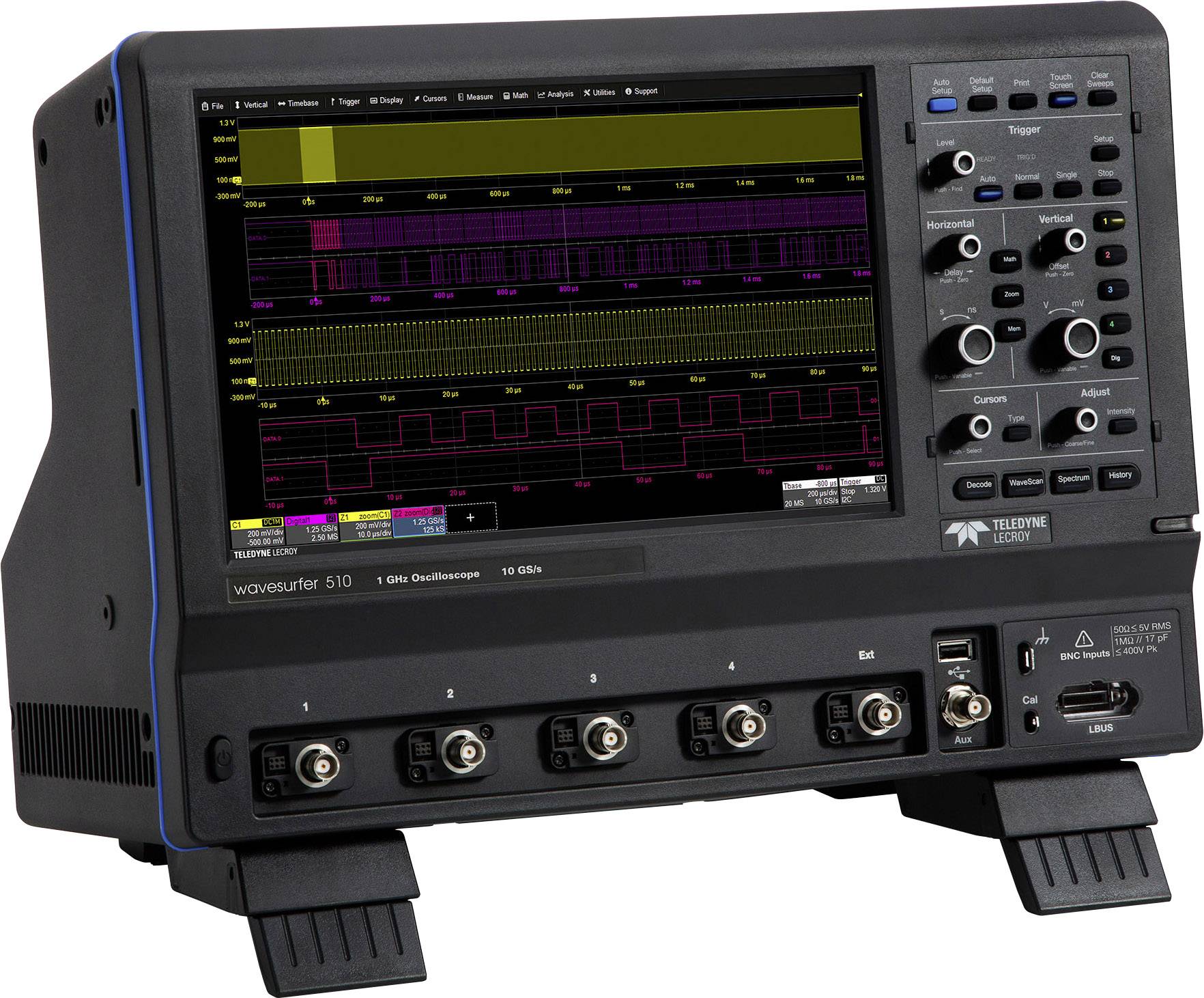
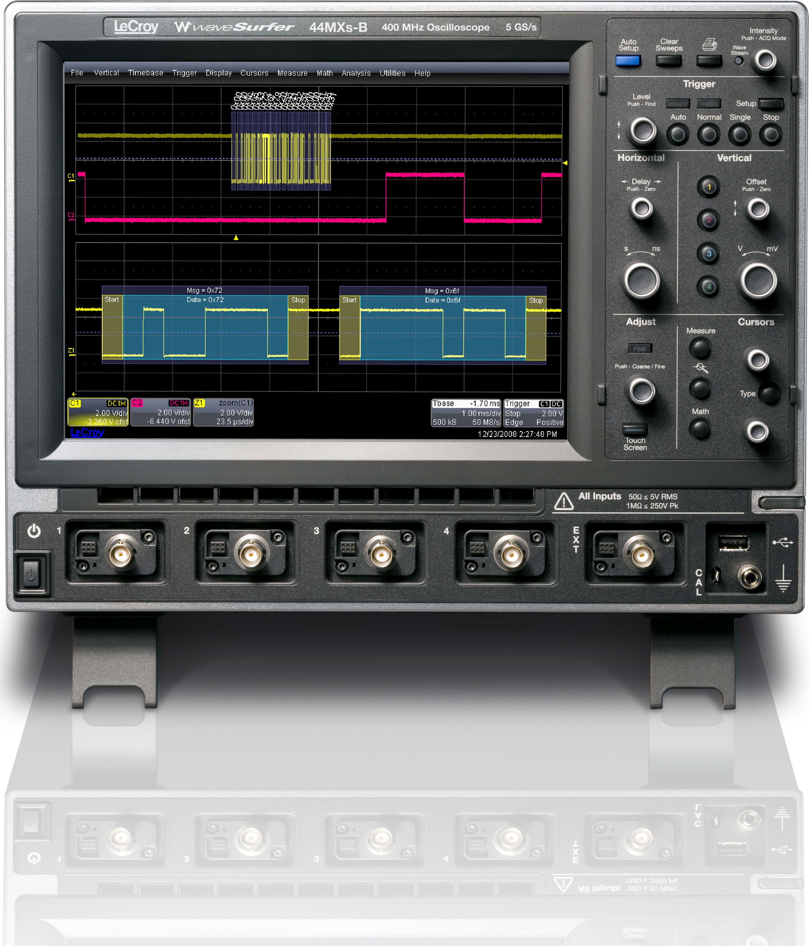
Parts- The LED driver previously described has been used as a light source in a FLIM setup. Finally frequency is increased and photodiode output modulation is monitored as an independent control of the driver’s optical response. The photodiode is then placed in front of the LEDs so that its output is modulated from 0 to 1 V. At this frequency the driver drives from ground to 50 mA at full depth of modulation. Resulting voltage at the bias-tee is a 0 to 500 mV sinewave voltage giving a 0 to 50 mA current sinewave in the LEDs. The AC sinewave is then powered on at 500 Hz and increased to 500 mV pp. The AC input control voltage has been set at 0 V first and the DC rose to 250 mV. Voltages are applied at the board input and the optical output measured with the photodiode. Methods- The driver board interconnects a custom-made LED board ( Figure 3). Optical signals have been acquired using a NewFocus 125 MHz ultrafast photodiode model 1801-FS and visualized using the oscilloscope. All electrical signals have been measured with a LeCroy WaveSurfer 44Xs, 400MHz and 2.5 GS/s oscilloscope. One output used was the fixed 5 V and the other was scaled to the forward voltage needed to drive the LEDs (usually 13 V). Power has been supplied by a B&K Precision triple output power supply. Both signals have been combined using a Mini-Circuit bias-tee model ZNBT-60-1W. Input signal to the circuit has been provided using a dual channel Hewlett-Packard (HP) model HP-3245a for the DC component and Aeroflex IFR2023 for the AC component. We chose to drive LEDs from Epitex, in particular L760-AU since they are high power (18 mW) and of wavelength of interest of our fluorophores. All capacitors are rated X7R for good frequency behavior.

The MOSFET is a ZETEX ZVN3306F with breakdown drain-source voltage of 60V, 150 mA maximum current, 5 Ω drain-source resistance and 35pF input capacitance.


 0 kommentar(er)
